Central Heating Three Way Valve Wiring Diagram design diagrom for firing
Why Is My Central Heating Noisy? BestHeating Advice Centre

ABSTRACT. This unique A-Z guide to central heating wiring systems provides a comprehensive reference manual for hundreds of items of heating and control equipment, making it an indispensable handbook for electricians and installers across the country. The book provides comprehensive coverage of wiring and technical specifications, and now.
Square D Model 6 Mcc Wiring Diagram Gallery Wiring Diagram Sample
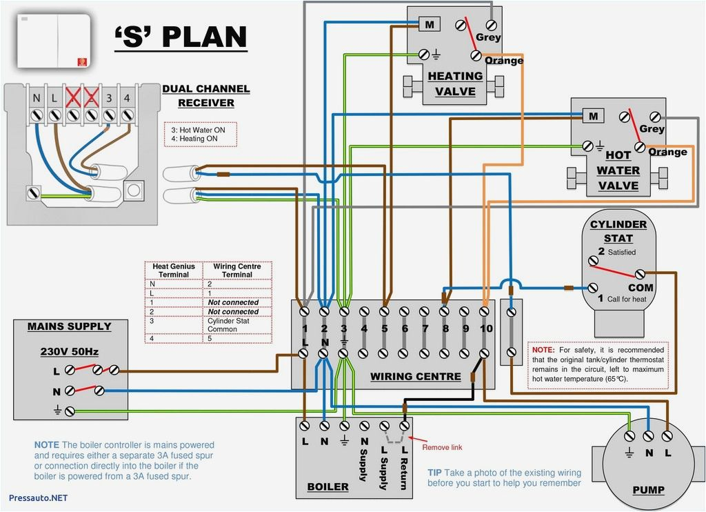
Operation - Hot water only. Power starts at terminal 3 (HW On) in the programmer. This passes via the wiring centre terminal 6 to the cylinder thermostat. If heat is required, power continues to terminal 8 in the wiring centre, and on to the boiler and pump. The valve is not powered at all, and the spring holds it in position B, so water from.
Modern Central Heating

G wire (fan) connected to the fan control to operate a blower in your HVAC system. Y1 wire (cooling) connected to the compressor/refrigerant system. Y2 wire (second stage cooling) connected to the 2nd stage cooling system. C wire (common) wire to complete the circuit and keep power flowing.
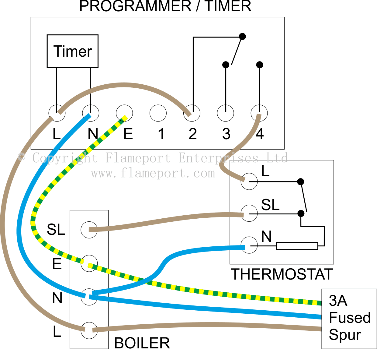
Domestic Central Heating System Wiring Diagrams; C, W, Y & S Plans Tim's Digi Musings

In summary, a wiring diagram is necessary for a Y-plan central heating system to provide a visual representation of the system's components and electrical connections. It ensures proper installation, efficient operation, and easier troubleshooting of any potential issues, ultimately leading to a more reliable and functional central heating.
Central Heating Bournemouth's Boiler & Heating Experts GWE

The majority of modern central heating systems make use of motorised valves, often called Zone valves, to divide different heating systems and hot water generation ie. Radiators, Under Floor Heating and Hot water cylinder.. 2C wiring schematic for single zone kit added to radiator system Terminal Block Section C 2C : Wiring schematic for.
Sediment central heating filter
Electrical wiring for central heating systems.Part 2 in the series looks at S plan wiring, a system which uses two separate valves. One valve for hot water,.
y plan diagram central heating Diagram Board

In this LearnElectrics video we will look at the wiring method of the Y Plan central heating system.This follows on from a previous video that looked at the.
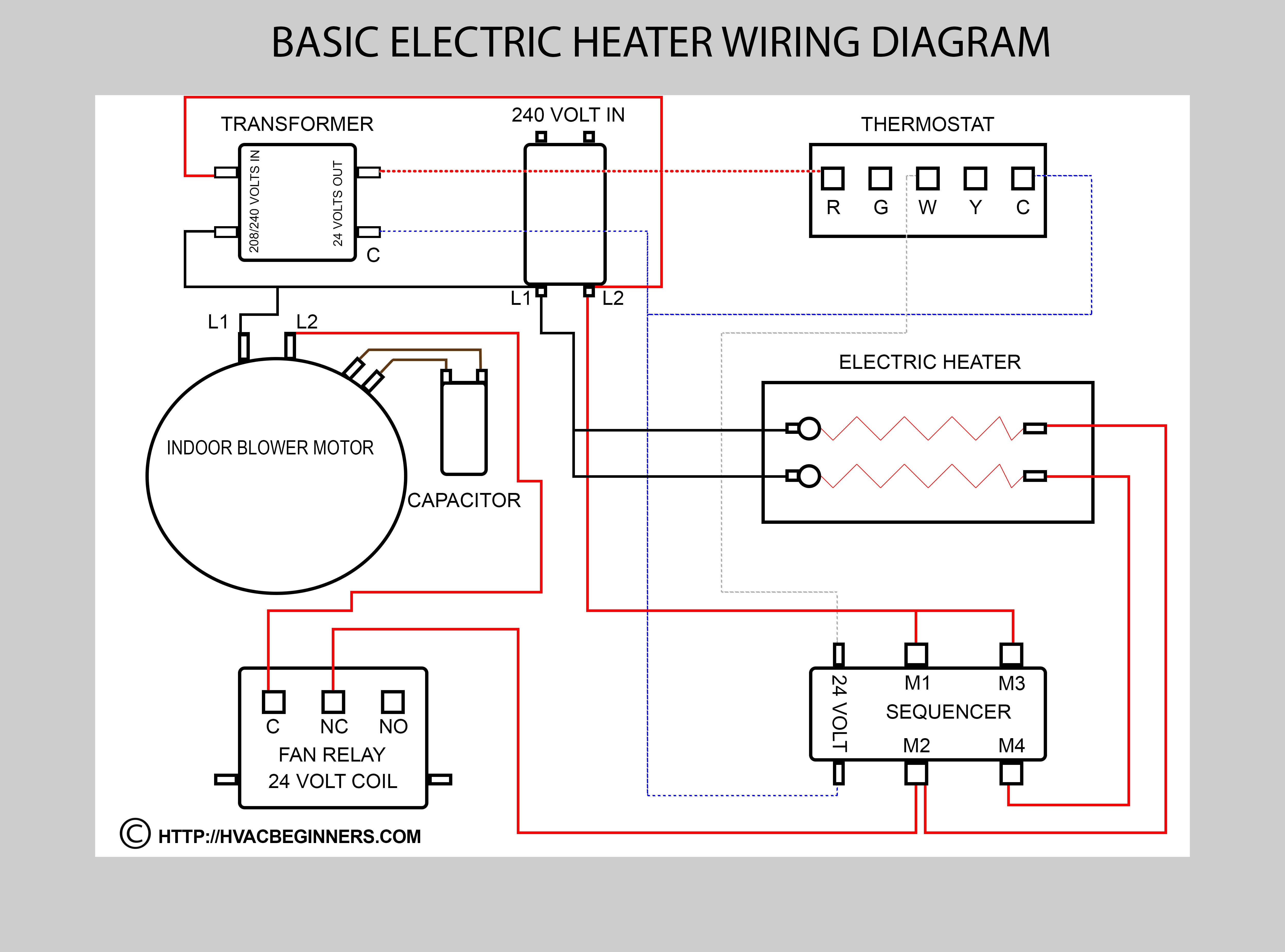
Hvac Training on Electric Heaters HVAC Beginners
S Plan Wiring Diagram. S Plan wiring diagrams for fully pumped central heating and hot water systems with pump overrun, includes connections for the boiler, hot water and central heating valves, tank stats, central heating wiring centre and room stats. Scroll to the bottom to download the s plan wiring diagram pdf.
Would nest learning thermostat be compatible with W plan system? Screwfix Community Forum

Electrical wiring for central heating systems.Part 3 in the series looks at Y plan wiring, a system which uses a single 3 port valve. This has one inlet and.
How to ensure efficiency of Central Heating system VAUNTE

In a gas central heating system, heat is distributed throughout a building through a series of components and processes. The system begins with a gas boiler, which uses fuel to heat water. This heated water is then pumped through a network of pipes to radiators located in each room of the building. The radiators are the main heat exchangers in.
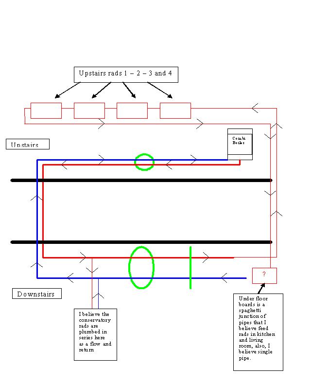
Central heating diagram DIYnot Forums
central heating boilers, combi boilers, gas boilers, oil boilers, gas central heating, heating engineers, boiler installation, boiler repair. Skip to content.. Greenstar i System Wiring Diagram 01.12.2016 onwards Download (3.49mb) Order hard copy. Please use the form to order printed copies of the document you selected..
Honeywell Rth5160 Wiring Diagram the wiring never sleeps
video 198 - y plan heating - wiring diagrams - how it works - easy to follow steps to understand y plan system Posted on June 10, 2023 To view this video, Y-PLAN HEATING , click on the link below
Central Heating Sebastian Seehofer

S Plan heating systems need to have a nice neat wiring center to enable everything from the plumbing up to work properly! I show you what the wires do and ho.
Central Heating Pipe Guide Heat Pump Source

Heating only. Terminal 4 on the programmer is active, which connects to wiring centre terminal 4 and on to the room thermostat. If heat is required, power continues to wiring centre terminal 7 which activates the boiler and pump. This also connects to the hot water cylinder thermostat C terminal, and if no hot water is required, terminal 2 on.
Wiring Diagram For A Central Heating System

Central Heating Thermostat (Room Stat) Y Plan Wiring Centre Terminal; Live: 4: Neutral: 3: Switched Live: 5: Programmer Y Plan Wiring Centre Terminal; Live: 1: Earth: 2: Neutral: 3: HW Off: 7: HW On: 6: CH On: 4: Y Plan wiring details for fully pumped central heating systems with pump overrun
Wiring Diagram Central Heating Underfloor Heating Thermostat Heating System, PNG, 500x500px

The diagram set includes wiring plans for a number of popular configurations of central heating systems, C Plan, W Plan, Y Plan, S Plan, S Plan+ etc. and you should select the most appropriate diagram that matches the components you have installed in your system along with what you're hoping to achieve in terms of controllability. Obviously.
.